Introduction and technical background
ipolog can read and write metadata from dwg drawing elements to support seamless import and export of ipolog layouts through AutoCAD. This metadata is stored as JSON objects in xdata structures (1001: IPOLOG_METADATA), which are attached to the DWG elements.
- The content of a Json-file is defined by a schema that is referenced in a “schema” attribute.
- Surface outlines are extracted from polylines with the corresponding Xdata attachment, working points use the transformation matrix of block references with the corresponding Xdata attachment.
- The Json-file object in the IPO_METADATA Xdata block can contain a “custom_data” object.
- The information contained in this object is provided as “custom_data” in the ipolog object model and can be used in colorizers or reports.
mceclip0.png
Schema
Areas
| Attribute | Data type | Description | Example |
| name | string | name of the area | TrimA1_R |
| area_type | string | MaterialArea, WorkerArea, ConveyorArea, BlockingArea, StructureArea | |
| station_name | string | station of the area | Station_01 |
| custom_data | object | oem data block | |
| for area type =”MaterialArea” additionally: | |||
| Attribute | Data type | Description | Example |
| layout_edge_index:int | int | edge for auto material placement | 0,1,2,3,... |
| layout_edge_inverted: bool | edge inverted | true / false |
Tags / Workingpoints
| Attribute | Data type | Description | Example |
| name | string | name of the tag | TrimA1_Wp |
| tag_type | string | WorkingPoint, ZoneReference, InfoPoint | |
| custom_data | object | oem datablock |
Please note:
- Pay attention to the spelling (upper and lower case) for the area_type and tag_type attributes. Only values from our schema definition are read as valid values.
- Values that differ from our definition are considered invalid and are not imported.
Procedure / Workflow
Under the “Plugins” module in ipolog 4 Workspace you will find the option of importing CAD layouts in .dwg-format into ipolog:
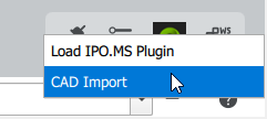
You can select your desired .dwg file by clicking on the “CAD import” button. After opening the .dwg file, the metadata of the layout objects attached with Xdata is read and displayed as a preview in the layout views (Layout Editor, MaterialZone Editor and in the 3D scene).
Drawing elements of the “Areas” and “Tags” schema are imported and displayed below the Layout Elements area.
For areas and tags, the following columns (metadata) are displayed:
| Status | Added: Areas have been added. Changed: Existing area attributes such as size, position or area type are changed. Identical: Existing area attributes and values remain unchanged Removed: Existing areas have been removed. You can also filter according to these four statuses by clicking on the desired status (radio button) |
| Name | The area name or tag name is the attribute used to compare changes to layout statuses. They are used as a unique object identifier. |
| Typ | For Areas: - MaterialArea - WorkerArea - ConveyorArea - BlockingArea - StructureArea For Tags: - WorkingPoint - ZoneReference - InfoPoint |
| Layer | Name of the layer from the .dwg drawing that is assigned to the object. |
| Details | Additional information that is displayed to the user. |
Commit / Cancel
After each import or re-import of a .dwg file, the changes are not applied directly, but are first visualized as a preview in the 3D scene and in the 2D layout views (Layout and MaterialZoneEditor). This preview also serves as a visual diff report.
Green means that new areas have been added (see status: added)
Yellow means that existing areas have been changed, e.g. in their size, position or area type (see status changed)
Red means that existing areas have been removed
You have a total of three options for selecting elements from the Areas or Tags section for inclusion in the layout:
- Checkbox (column *): This allows you to activate / deactivate certain entries
- All: Select all entries
- None: Select no entries
Commit:
If you like to transfer the selected entries to the ipolog layout, click on the Commit button.
As soon as a layout transfer has been carried out, the entries displayed in the list are cleared.
Cancel:
Cancels the transfer process to the layout and loads the last saved data status
Create Facility:
- reads all drawing elements of the imported layout
- creates surrounding geometries that can be inserted and displayed as a facility (template) in the layout.
- created facilities are added to the catalog / facilities tab and can be inserted into the layout with "Insert".
Hints and tips:
The path to the .dwg file is relative, i.e. you can edit the layout in ACAD in parallel, save it and reload it directly and display the changes directly by clicking in the input field and confirming with Enter.